Biomechanical system elements: axial rotation profiling model with preset angular orientation parameters
Фотографии:
ˑ:
Dr.Hab., Professor V.I. Zagrevskiy1, 2
Dr.Hab., Professor O.I. Zagrevskiy 2
1Mogilev State University n.a. A.A. Kuleshov, Mogilev, Belarus
2National Research Tomsk State University, Tomsk
Keywords: sport exercises, model, rotation matrix, computational experiment, biomechanical system.
Background. Today physical action biomechanics are considered fundamental for profiling technical training systems and this is the reason why sport theoreticians and practitioners give an increasing priority to the athletic motor skills biomechanics and training/ educational process implications of the relevant biomechanical studies and findings [1]. Presently sport communities show a growing interest to the computerised 3D presentations of physical actions in sports [2]. For further progress in the computerised 3D studies of biomechanical system movements, the researchers make an emphasis on a biomechanical system rotation in the OUVW local coordinate system. For expansion of the 3D geometry of motor skills, the pronator/ supinator muscle actions in upper and lower limbs are to be duly modelled.
Objective of the study was to develop a technological framework for the mathematical provisions and software to visualize the biomechanical system’s 3D position and orientation by the relevant computer tools.
Study results and discussion
Object model
We applied a model rectangular prism physically connected with the OUVW local coordinate system placed into absolutely immovable reference system OXYZ: see Figure 1А.
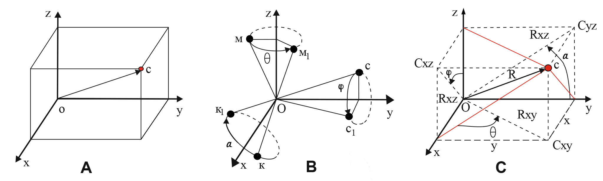
Figure 1. Modelled object (А), positive rotation (В), and turning angles (a, j, q) in the elementary rotation matrix (С)
In the computer presentation of the 3D image on the screen, the rotation axis goes through the mass centre of the modelled object with Oy axis pointed down and Oz axis going perpendicular and inside the screen. Final orientation of the modelled object was predetermined by a complex rotation matrix with preset local axes rotation angles of the object (OUVW) in relation to the absolute reference coordinate system OXYZ. In the starting position prior to the modelled object being rotated, both of the coordinate system loci (OUVW and OXYZ) and their digital axes match.
Matrix rotation/ turn operations
Mathematical solution of the subject task was based on the relevant matrix (array) operations as provided by the relevant studies [3, 4] that require the following rules to be met to obtain a resultant rotation matrix [4]:
- Since both of the coordinate systems match in the starting position, the rotation matrix in this position is reduced to a unit matrix of 3х3 size.
- When the OUVW system turns around one of its key axes, the prior resultant rotation matrix is multiplied on the left side of the relevant elementary rotation matrix.
- The movable OUVW coordinate system rotation around one of its key axes may be presented by the elementary rotation matrix being multiplied on the prior resultant rotation matrix.
Based on the above rules, the rotation matrix resulting from a succession of elementary turns (first the j angle turn about Oy axis; then the q angle turn about Oz axis; followed by a angle turn about Ou axis: see Figure 1) may be presented as follows:
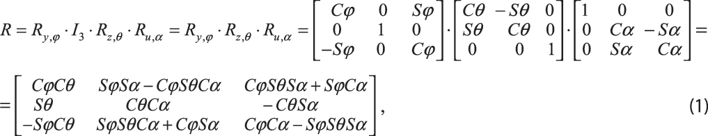
Where.
Given on Figure 2 hereunder is the computer presentation of the modelled object movement.
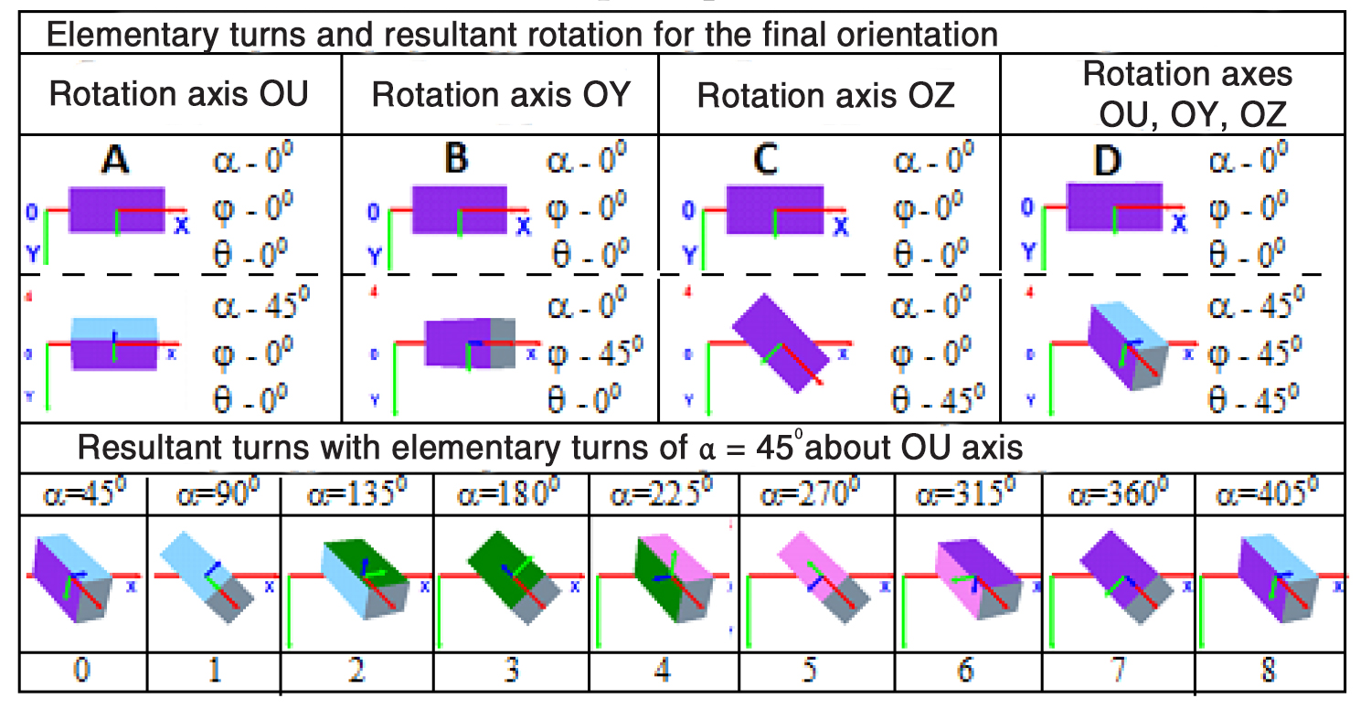
Figure 2. Presentation of the required object orientation using the elementary (А-C) and resultant (D) rotation matrixes, with the rotation process being modelled by snapshots 1-8
Elementary turns and resultant rotation for the final orientation
Rotation axis OU Rotation axis OY Rotation axis OZ Rotation axes OU, OY, OZ
Resultant turns with elementary turns of α = 450 about OU axis
The elementary rotation matrices Ry,j and Rz,q will ensure the modelled object being moved from the starting position to the required orientation and position; with the object rotation about the local Ou axis (modelling the pronator/ supinator muscle movements) being secured by Ru,a matrix. Note that I3 matrix is the unit matrix of 3х3 size.
Given on Figure 2 are the results of the computational experiment designed to compute the modelled object’s fixed positions when it is rotated from the starting position by j=450, q=450 and a=450 angles towards the final turn matrix R. Since both of the coordinate systems (OXYZ and OUVW) match in the starting position, j=00, q=00, a=00. With every step of the movement fixed by the relevant snapshot (see Figure 2, snapshots 1-8), the following successive operations will be made:
- Compute the object’s starting position and orientation.
- Rotate the object in the required position and orientation by the constant elementary turn angles j and q towards the resultant rotation matrix R.
- Visualize the object’s position and orientation on the screen.
- Change the rotation a angle in the Ru,a matrix by the elementary steps of the a rotation about Ou axis.
- Turn back to the above item 1 to compute the next snapshot in the movement sequence.
The elementary computation step will be reiterated as long as required by the task conditions and stopped when the preset finishing point is attained by the computing process.
Conclusion
- The computer software designed to model movements of an object gives the means to adequately visualize the results of mathematical operations with the required 3D kinematic parameters of the rotating object.
- The required 3D orientation of an object may be modelled either by multiplication of the elementary rotation matrixes or proceeding from the resultant rotation matrix.
- Rotation of the biomechanical system elements about a longitudinal axis of the relevant element (modelling the pronator/ supinator muscle movement) with the preset angular orientation may be attained by the following two movements:
- The element may be rotated about axes of the immovable reference coordinate system to attain the required angular orientation of the longitudinal axis of the element.
- Alternatively the element may be rotated in the OUVW local coordinate system around the relevant axis to attain the required angular orientation of the longitudinal axis of the element (modelling the pronator/ supinator muscle movement).
- Studies in the modern 3D sport biomechanics may be furthered by computer tools to model movement visualizing geometric transformations including the following:
- Object rotation about a randomly selected axis determined by the movement parameters subject to computation operations so as to profile every biomechanical system element rotation angles and visualize them for the subject sport exercises.
- Object rotation about a randomly selected point with the relevant computation procedures used to design a model composed of interconnected objects, including a biomechanical system model.
References
- Gaverdovskiy Y.K. Obuchenie sportivnyim uprazhneniyam. Biomekhanika. Metodologiya. Didaktika [Teaching Exercise. Biomechanics. Methodology. Didactics]. Moscow: Fizicheskaya kultura publ., 2007, 912 p.
- Zagrevskiy V.I., Zagrevskiy O.I. Geometricheskie preobrazovaniya prostranstvennoy modeli biomekhanicheskoy sistemy [Geometric transformations of spatial model of biomechanical system]. Teoriya i praktika fiz. kultury, 2016, no. 8, pp. 83-85.
- Rogers D., Adams J. Matematicheskie osnovy mashinnoy grafiki: Per. s angl. [Mathematical foundations of computer graphics. Transl. from Engl.]. Moscow: Mir publ., 2001, 604 p.
- Fu K., Gonsales R., Li K. Robototekhnika: Per. s angl. [Robotics: Trans. from English]. Moscow: Mir publ., 1989, 624 p.
Corresponding author: o.zagrevsky@yandex.ru
Abstract
The article considers a mathematical apparatus for computer modelling of pronator/ supinator muscle movements in a human body and demonstrates how the axial rotation of a biomechanical system element may be formally described using a set of matrix operations to profile rotation of a movable coordinate system around its own axes. Objective of the study was to develop a technological framework for the mathematical provisions and software to visualize the biomechanical system’s 3D position and orientation by the relevant computer tools. We have developed a computer software to visualize the 3D position and axial rotation of the model rectangular prism with the preset angular orientation parameters. The software was designed using Visual Basic 2010 Express algorithmic language in Visual Studio 2013 interactive design environment. It is the matrix description method to describe the 3D positions of the moving object plus the matrix multiplication method for presetting the necessary orientation and rotation that were applied to form a mathematical core of the software. The study shows that the human limb rotation and pronation may be modelled by a certain sequence of matrix multiplication operations i.e. by the elementary rotation matrixes being multiplied.


 Журнал "THEORY AND PRACTICE